
Order Code | AX9 |
|---|---|
LED Engine | Titan LED Engine |
Colors | RGBMintAmber |
Total LED Power | 105 W |
LED Power Draw | 70 W |
Luminous Flux 2700K | 2 844 Lumens |
Luminous Flux 3200K | 3 214 Lumens |
Luminous Flux 5500K | 3 047 Lumens |
Light Output 2700 K @ 1m | 41 755 Lux |
Light Output 3200 K @ 1m | 47 078 Lux |
Light Output 5500 K @ 1m | 44 355 Lux |
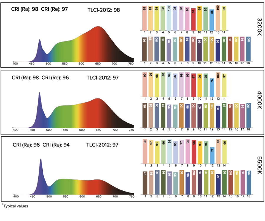
CRI (Ra)/ TLCI 3200- 6500 K | ≥96 |
Beam Angle | 13° |
Field Angle | 25° |
Strobe | 0 – 25 Hertz |
Pixels | 1 |
Battery Runtime | up to 20 hours |
Battery Lifetime | 70 % after 300 cycles |
Charging Time (nominal) | 5 hours |
AC Input | 100-240 VAC, 50/60 Hz, |
AC Connector | PowerCON TRUE1 IN/OUT |
Wired DMX | Yes (via 5-pin XLR) |
CRMX Receiver | Built-in |
BluetoothBridge BTB | Built-in |
Wireless Protocols | CRMX, UHF, Bluetooth, WiFi |
Wireless Range | CRMX/UHF up to 300 m / 330 yds |
Infrared Control | Yes |
IP Rating | IP65 |
Ambient Operating Temperature | 0 – 40 °C / 32 – 104 °F |
Weight | 5.66 kg / 12.5 lb |
Dimensions L x W x D | 175 mm x 222 mm x 256 mm / |
Mounting Options | AirlineTrack |
All specifications provided are typical values and may be subject to change without prior notice.