AX3 LightDrop

Technical Specifications

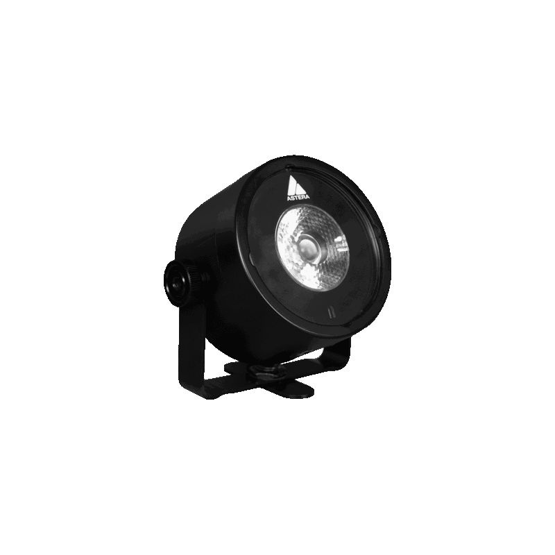
Please note that due to a component shortage, we had to do internal changes to AX3 LightDrop and units manufactured after September 2022, they have the BTB feature built-in and are now called AX3-BTB.

Order Code

AX3-CRMX

AX3-BTB

LED Engine

RGBW

RGBW

Colors

RGBW

RGBW

Total LED Power

15 W

15 W

Luminous Flux 3200K

430 Lumens

430 Lumens

Light Output 3200 K @ 2m

1 300 Lux

1 300 Lux

CRI (Ra)/ TLCI 3200- 6500 K

≤88

≤88

Beam Angle

13°

13°

Field Angle

22°

22°

Strobe

0 – 25 Hertz

0 – 25 Hertz

Pixels

1

1

Battery Runtime

up to 20 hours

up to 20 hours

Battery Lifetime

70 % after 300 cycles

70 % after 300 cycles

Charging Time (nominal)

7 hours

7 hours

DC Input

5 VDC – 2.5 A

5 VDC – 2.5 A

DC Connector

5.5 mm x 2.5 mm

5.5 mm x 2.5 mm

Wired DMX

No

No

CRMX Receiver

Built-in

Built-in

BluetoothBridge BTB

No

Built-in

Wireless Protocols

CRMX, UHF

CRMX, UHF, Bluetooth, Wifi

Wireless Range

CRMX/UHF up to 300 m / 330 yds

CRMX/UHF up to 300 m / 330 yds Bluetooth up to 3 m / 3.3 yds

Infrared Control

Yes

Yes

Housing Material

Aluminium & Polycarbonate

Aluminium

IP Rating

IP65 (only with Waterproof Protection Cover (AX3-SP))

IP65 (only with Charging Socket Cover (AX3-SP)

Ambient Operating Temperature

0 – 40 °C / 32 – 104 °F

0 – 40 °C / 32 – 104 °F

Weight

0.68 kg / 1.4 lbs

0.68 kg / 1.4 lbs

Dimensions with bracket (L x W x D)

120 mm x 59 mm x 114 mm / 7.4” X 2.3” X 4.4”

120 mm x 59 mm x 114 mm / 7.4” X 2.3” X 4.4”

Dimensions without bracket (Ø x H)

Ø95 mm x 59 mm / Ø3.7” x 2.3”

Ø95 mm x 59 mm / Ø3.7” x 2.3”

Mounting Options

Magnet, 3x M4 threads, Bracket (with 1x 3/8" – 16 UNC thread, 2x 1/4" 20 UNC threads)

Magnet, 3x M4 threads, Bracket (with 1x 3/8" – 16 UNC thread, 2x 1/4" 20 UNC threads)

-

All specifications provided are typical values and may be subject to change without prior notice.

What's in the Box

RF Characteristics

For AX3 LightDrop

Wireless Modules

Modulation

ERP (Transmitter)

Channel Count

EU: UHF***(863-870MHz)

FHSS

<25mW

47

USA: UHF (917-922.20MHz)

FHSS

<25mW

53

AUS: UHF (922.30-927.50MHz)

FHSS

<25mW

53

SGP: UHF (920.50-924.50MHz)

FHSS

<25mW

41

KOR: UHF (917.9-921.5MHz)

FHSS

<25mW

10

RUS: UHF (868.75-869.12MHz)

FHSS

<25mW

6

JPN: UHF (922.80-926.40MHz)

FHSS

<25mW

19

CRMX (2402-2480MHz)

FHSS

79

***General allocation of frequencies for use by short-range radio applications Spectrum usage regulations:

Frequency range in MHz1)

Maximum equivalent radiant power (ERP)Maximum equivalent radiant power (ERP)

Additional parameters / frequency access and interference mitigation techniques

865 – 868

25 mW

Requirements for frequency access and mitigation techniques3) Alternatively, a maximum duty cycle2) of 1% can be used.

868,0 – 868,6

25 mW

Requirements for frequency access and mitigation techniques3) Alternatively, a maximum duty cycle2) of 1% can be used.

868,7 – 869,2

25 mW

Requirements for frequency access and mitigation techniques3) Alternatively, a maximum duty cycle2) of 0.1% can be used.

869,40 – 869,65

500 mW

Requirements for frequency access and mitigation techniques3) Alternatively, a maximum duty cycle2) of 10% can be used.

869,7 – 870,0

25 mW

Requirements for frequency access and mitigation techniques3) Alternatively, a maximum duty cycle2) of 1% can be used.

Conditions pour l’accès à la fréquence et les techniques d’atténuation3) Alternativement, un cycle de service maximum2) de 1 % peut être utilisé.

RF Characteristics

For AX3 – BTB LightDrop

Wireless Modules

Modulation

ERP (Transmitter)

Channel Count

EU: UHF***(863-870MHz)

FHSS

<25mW

47

USA: UHF (917-922.20MHz)

FHSS

<25mW

53

AUS: UHF (922.30-927.50MHz)

FHSS

<25mW

53

SGP: UHF (920.50-924.50MHz)

FHSS

<25mW

41

KOR: UHF (917.9-921.5MHz)

FHSS

<25mW

10

RUS: UHF (868.75-869.12MHz)

FHSS

<25mW

6

JPN: UHF (922.80-926.40MHz)

FHSS

<25mW

19

CRMX (2402-2480MHz)

FHSS

79

Bluetooth 5.0 LE (2402-2480MHz)

FHSS

10mW (BLE)

40

WiFi (2412-2472MHz)

DSSS, OFDM

<100mW

13

***General allocation of frequencies for use by short-range radio applications

Frequency range in MHz1)

Maximum equivalent radiant power (ERP)

Additional parameters / frequency access and interference mitigation techniques

865 – 868

25 mW

Requirements for frequency access and mitigation techniques3) Alternatively, a maximum duty cycle2) of 1% can be used.

868,0 – 868,6

25 mW

Requirements for frequency access and mitigation techniques3) Alternatively, a maximum duty cycle2) of 1% can be used.

868,7 – 869,2

25 mW

Requirements for frequency access and mitigation techniques3) Alternatively, a maximum duty cycle2) of 0.1% can be used.

869,40 – 869,65

500 mW

Requirements for frequency access and mitigation techniques3) Alternatively, a maximum duty cycle2) of 10% can be used.

869,7 – 870,0

25 mW

Requirements for frequency access and mitigation techniques3) Alternatively, a maximum duty cycle2) of 1% can be used.

1) The use of adjacent frequency bands within this table as a single fre- quency band is permitted, provided that the specific conditions for each of these adjacent frequency bands are met. 2) „duty cycle“ means the ratio of Σ(Ton)/(Tobs) expressed as a percentage, where ‚Ton‘ is the ‚on-time‘ of a single transmitting device and ‚Tobs‘ is the observation period Ton is measured in an observation frequency band (Fobs). Unless otherwise specified in this general allocation, Tobs is a conti- nuous period of one hour and Fobs is the applicable frequency band in this general allocation (table). 3) Frequency access and interference mitigation techniques shall be used whose performance level at least meets the essential requirements of Directive 2014/53/EU or the Radio Equipment Act (FuAG). Where relevant techniques are described in harmonised standards, the references of which have been published in the Official Journal of the European Union pursuant to Directive 2014/53/EU, or parts thereof, performance shall be ensured which is at least equivalent to those techniques.