Order Code | AST-QUKSP |
|---|---|
LED Engine | Titan LED Engine |
Colors | RGBMintAmber |
Output Gain | Yes |
Total LED Power | 60 W |
LED Power Draw | 38 W |
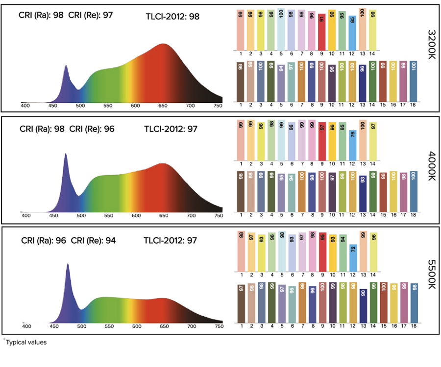
CRI (Ra) / TLCI 3200 – 6500 K* | ≥96 |
Strobe | 0 – 25 Hertz |
Battery Runtime | up to 20 hours |
Battery Runtime (max. Brightness) | 4.5 hours |
Battery Lifetime | 70 % after 500 cycles |
Charging Time (nominal) | 5 hours |
AC Input | 100 – 240 VAC, 50/60 Hertz |
AC Connector | PowerCON TRUE1 IN/OUT |
Power Consumption (max.) | 50 W |
Wired DMX | Yes |
CRMX Receiver | Built-in |
BluetoothBridge BTB | Built-in |
Wireless Protocols | CRMX, UHF, Bluetooth, WiFi |
Wireless Range | CRMX/UHF up to 300 m / 330 yds |
RDM Support | Wireless and wired |
Infrared Control | Yes |
PrepBox Compatible | Yes |
IP Rating unwired | IP65 |
IP Rating wired | IP65 |
Ambient Operating Temperature | 0 – 40 °C / 32 – 104 °F |
Weight | 3450 g / 7.6 lbs |
Dimensions (L x W x D) | 164 mm x 164 mm x 182 mm / |
Mounting Options | AirlineTrack, 3/8" – 16 UNC thread, |
Technical Specifications
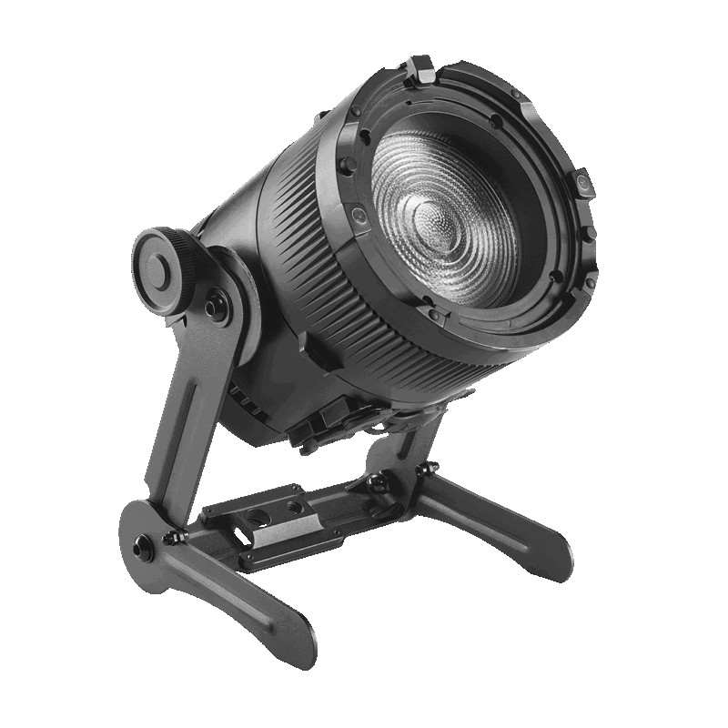
What's in the Box
- 1 x QuikSpot (AST-QUKSP)
- 1 x QuikSpot Yoke (AST-QUKSP-YK)
Typical Spectras
RF Characteristics
Wireless Modules | Modulation | ERP (Transmitter) | Channel Count |
|---|---|---|---|
EU: UHF***(863-870 MHz) | FHSS | < 25 mW | 47 |
USA: UHF (917-922.20 MHz) | FHSS | < 25 mW | 53 |
AUS: UHF (922.30-927.50 MHz) | FHSS | < 25 mW | 53 |
SGP: UHF (920.50-924.50 MHz) | FHSS | < 25 mW | 41 |
KOR: UHF (917.9-921.5 MHz) | FHSS | < 25 mW | 10 |
RUS: UHF (868.75-869.12 MHz) | FHSS | < 25 mW | 6 |
JPN: UHF (922.80-926.40 MHz) | FHSS | < 25 mW | 19 |
CRMX (2402-2480 MHz) | FHSS | – | 79 |
Bluetooth 5.0 LE (2402-2480 MHz) | FHSS | 10 mW (BLE) | 40 |
WiFi (2412-2472 MHz) | DSSS, OFDM | < 100 mW | 13 |
***General allocation of frequencies for use by short-range radio applications Spectrum usage regulations:
Frequency range in MHz | Maximum equi- valent radiant power (ERP) | Additional parameters / frequency access and interference mitigation techniques |
|---|---|---|
865 – 868 | 25 mW | Requirements for frequency access and mitigation techniques3) Alternatively, a maximum duty cycle2) of 1% can be used. |
868,0 – 868,6 | 25 mW | Requirements for frequency access and mitigation techniques3) Alternatively, a maximum duty cycle2) of 1% can be used. |
868,7 – 869,2 | 25 mW | Requirements for frequency access and mitigation techniques3)Alternatively, a maximum duty cycle2) of 0.1% can be used. |
869,40 – 869,65 | 500 mW | Requirements for frequency access and mitigation techniques3) Alternatively, a maximum duty cycle2) of 10% can be used. |
869,7 – 870,0 | 25 mW | Requirements for frequency access and mitigation techniques3) Alternatively, a maximum duty cycle2) of 1% can be used. |
1) The use of adjacent frequency bands within this table as a single frequency band is permitted, provided that the specific conditions for each of these adjacent frequency bands are met. 2) „duty cycle“ means the ratio of Σ(Ton)/(Tobs) expressed as a percentage, where ‚Ton‘ is the ‚on-time‘ of a single transmitting device and ‚Tobs‘ is the observation period Ton is measured in an observation frequency band (Fobs). Unless otherwise specified in this general allocation, Tobs is a continuous period of one hour and Fobs is the applicable frequency band in this general allocation (table). 3) Frequency access and interference mitigation techniques shall be used whose performance level at least meets the essential requirements of Directive 2014/53/EU or the Radio Equipment Act (FuAG). Where relevant techniques are described in harmonised standards, the references of which have been published in the Official Journal of the European Union pursuant to Directive 2014/53/EU, or parts thereof, performance shall be ensured which is at least equivalent to those techniques.